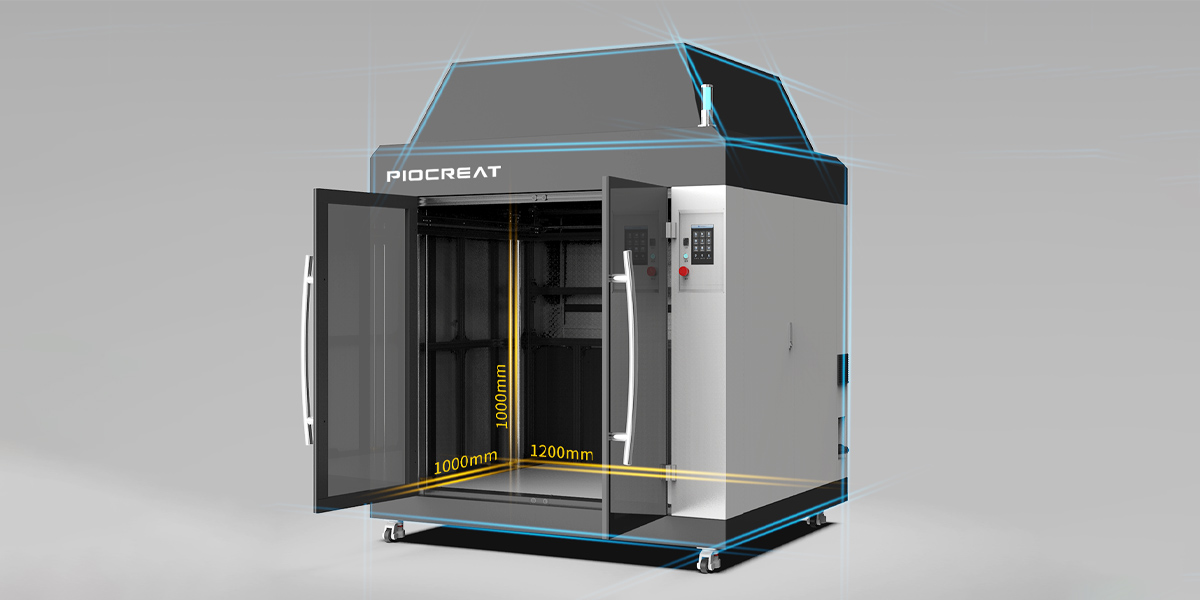
G40 installation environment and machine tool positioning requirements for large pellets 3D printing center?
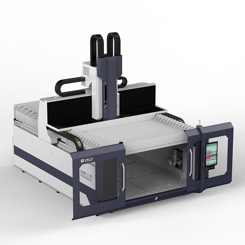
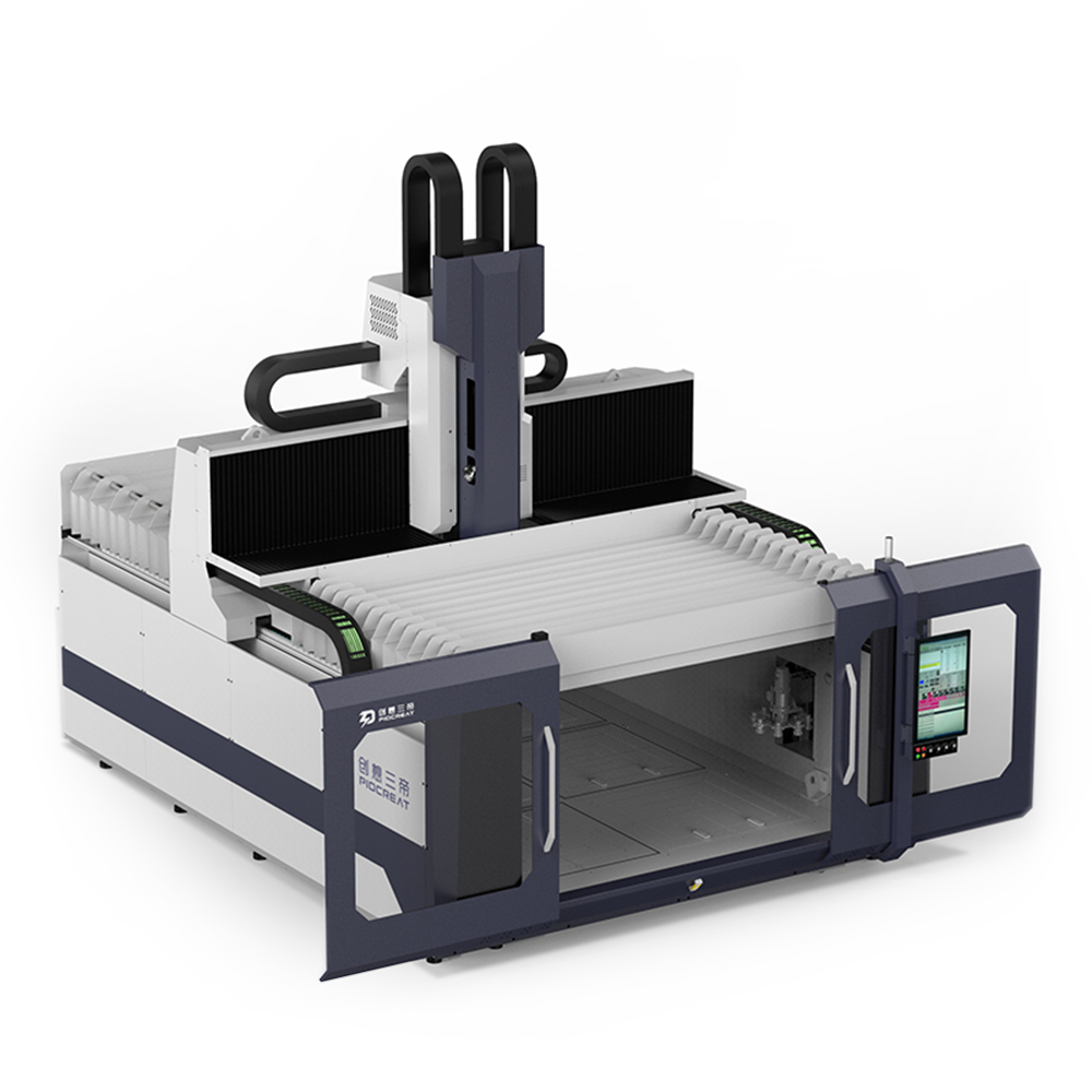
Piocreat 3D printing and processing center for large granular materials G40 has 5962 × four thousand two hundred and twenty × With a size of 4800mm, it is a large
pellet 3D printing and processing center, covering an area of 5962 square meters × six thousand and twenty × 4800mm, G40 has relatively strict requirements for installation and machine tool positioning.
1. Environmental requirements around installation foundation
The machinery shall be avoided to be installed in places where it is easy to conduct vibration, heavy moisture, close to heat source, corrosive gas and direct sunlight.
Specific requirements:
(1) Allowable temperature: 0 ° C ~ 45 ° C
(2) Relative humidity requirements: the humidity change must be less than 90%, and there must be no moisture condensation.
(3) The environmental humidity and temperature shall be controlled as much as possible, and the environmental conditions shall not change rapidly.
(4) The machine shall not be placed in a dust environment to avoid dust accumulation.
(5) It is forbidden to place the machine in an environment containing acid, alkali and other corrosive gases or liquids.
(6) It is forbidden to place the machine in an environment with strong magnetic field and strong static electricity.
(7) It is forbidden to place the machine in a hot light source or an environment where the sun can shine directly.
(8) It is forbidden to place the machine in an environment with ordinary and frequent vibration.
(9) It is forbidden to place the machine near the source of electrical noise (such as air blowing compressor).
2. Machine tool installation area (please refer to the machine tool specification parameter table)
3. Machine tool positioning
(1) After the machine tool is transported to the specified position, put down the machine slowly.
(2) When the bottom of the machine is about 100mm away from the ground, the installation personnel align the center of the anchor pad iron with the anchor screw hole at the bottom of the machine, and then place it on the ground.
(3) Slowly lower the machine until the bottom of the machine is in full contact with the floor pad iron.
4. Machine installation
(1) Adjust the foundation pad iron and use a jack if necessary.
(2) It is required that the machine tool has a three-phase (50Hz / m2) power supply with more than 250V transformer, which must be connected to the machine tool separately. The voltage fluctuation must be within ± 10% and remain relatively stable, and there are safe grounding measures, otherwise it will affect the normal operation of the NC system. a. The machine equipment is grounded separately from the plant power supply system. b. The grounding conductor must use insulated wire of more than 16 mm2. c. Use copper bar φ 30 * 1000 (mm) as the grounding electrode must be buried vertically under the ground. If it is blocked by {rock, it can be buried laterally at a depth of more than 1000mm underground.
(3) Remove the fixed block of the x-axis and the y-axis in the shipping mode, A. remove the fixed block of the y-axis, and B. remove the fixed block of the y-axis in the shipping mode.
(4) Clean
a. Power failure
b. In order to prevent corrosion, the unpainted parts of the machine are coated with anti rust oil before leaving the factory, so it is necessary to wipe them with cotton cloth dipped with cleaning solvent. During cleaning, pay special attention not to flow the cleaning solvent into the main shaft or other three shafts.
c. After cleaning, apply another layer of lubricating oil on the original surface.
(5) Horizontal adjustment
a. Two levels must be used for horizontal adjustment, with an accuracy of 0.02mm/grid.
b. The absolute level of the level itself must be confirmed before adjustment. The method is as follows.
c. Place the level at a fixed point on the workbench.
d. After the bubble is stable, record its position, and then rotate it by 180 °. When the bubble stops, it must be compared with 0 °, and the tolerance is allowed to be within 1 / 3 grid.
e. Place the level in the center of the workbench, and its placement position is shown in the figure.
f. Adjust the anchor bolt and adjust the horizontal bubble to the middle point.
g. Move the y-axis to measure the front and rear two points, observe the bubble direction of the two levels, and then decide to adjust the foot screw.
h. Adjust the anchor screw at the lower part of the bubble clockwise until the level on the X and Z # planes at the front and rear points is within 1 / 4 grid, and the level on the Y and Z planes is within 0.02m/m.
i. After adjustment, move the y-axis to the center of the stroke, and the horizontal bubbles on the x-z and Y-Z planes must be in the center.
j. Move the front, middle and rear points of y-axis, and measure that the maximum difference is 0.02mm/m (about 3 grids).
k. Move the front, middle and rear points of x-axis, and measure that the maximum difference is 0.02mm/m (about 3 grids).